- Type your FortiGate Name or IP Adress in Browser and then Press Enter
- Click Yes
- Type Name and Password, and then Click Login
- Go to Web Filter > FortiGuard – Web Filter > Override, and then Click Edit
- Click Edit
- Configure Override Rule, and then Click OK
Showing posts with label Fortigate. Show all posts
Showing posts with label Fortigate. Show all posts
Friday, September 17, 2010
FortiGate – Configure Web Override Rule


Fortigate Service TTL
This article describes how to change the session TTL for a specific port. In this example it is telnet.
Protocol 6 is TCP.
Protocol 17 is UDP.
If you leave the protocol on 0, it is valid for all protocols.
config system session-ttl
 set default 1800
 config port
 edit 23
  set protocol 6
  set timeout 3600
  set start-port 23
  set end-port 23
 next
end
The session timeout is in seconds.
Protocol 6 is TCP.
Protocol 17 is UDP.
If you leave the protocol on 0, it is valid for all protocols.
Fortigate command tree
If you want to know all possible commands from the command line of your Fortigate firewall, then log in using SSH and type the following command:
treeNow you get the complete command tree with all options and all choices.
Advanced IPSEC VPNs
Most of the time when you create site-to-site VPN tunnels the Phase 2 Quick Mode Selector just doesn't cut it. In FortiOS 2.8 you were able to choose between manually entering source and destination addresses or selecting objects from a drop-down list. This feature is absolutely essential when creating VPNs that contain discontiguous subnets. A good example:
Source subnets: 172.16.1.0/24 and 192.168.1.0/24, destination subnets: 172.16.99.0/24 and 10.1.1.0/24.
In FortiOS 3.0 up to MR6 the drop-down option no longer exists in the GUI. However you can still pop the hood and get at the internals using the CLI. Here's how:
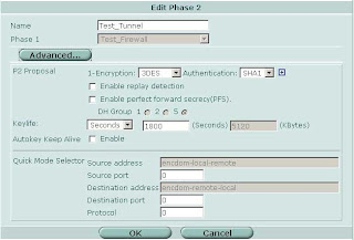
Source subnets: 172.16.1.0/24 and 192.168.1.0/24, destination subnets: 172.16.99.0/24 and 10.1.1.0/24.
In FortiOS 3.0 up to MR6 the drop-down option no longer exists in the GUI. However you can still pop the hood and get at the internals using the CLI. Here's how:
- In the GUI define the local and remote subnets for the VPN
- Group local and remote subnets into separate address groups (e.g. "encdom-local-remote" and "encdom-remote-local")
- On the CLI
- # config vpn ipsec phase2 (or #config vpn ipsec phase2-interface if you are using interface mode)
- # set src-addr-type name
- # set src-name encdom-local-remote (the address group containing your local subnets)
- # set dst-addr-type name
- # set dst-name encdom-remote-local (the address group containing the remote subnets)
- # end

Dynamic Routing Protocols over IPSEC VPNs
Start by building your site-to-site VPN tunnels in interface mode (see here for more info on interface mode). Important Note: Make sure your Phase 2 quick mode selectors are set to 0.0.0.0/0.

Once you have your tunnels configured go to Network -> Interface and expand the blue triangle next to the interface to which you have the tunnel attached:

Something which is not immediately obvious is that you can define an IP address on the tunnel interface. Edit the tunnel interface and assign unique IP addresses (i.e. something that is not in use on your network, typically a private IP) for the local and remote IP:

On the other side of the tunnel perform the same operation, reversing the settings for local and remote IP.
Now on to the OSPF side of things. Under Router -> Dynamic -> OSPF define Area 0.0.0.0 (the backbone). Then configure a Network which includes the network of the tunnel interface and place it in area 0.0.0.0. Under Interfaces create an interface tied to the tunnel interface. You can leave the IP as 0.0.0.0.

Repeat the same on the other end and you should see your routes starting to come in as OSPF dynamic routes. To control which routes are advertised you can redistribute networks under the Advanced Options in OSPF. You can also apply router access lists to filter networks from being advertised. More on router access lists (used for OSPF) and router prefix lists (used for BGP) in another post.
Filtering Dynamic Routes
Sometimes it is necessary to filter dynamically learned routes from being advertised to your network. To do this on the Fortigate platform you can utilize router access lists and router prefix lists. Router access lists are used for filtering OSPF routes, router prefix lists are used for filtering BGP routes. Below are examples for each type of access list. Configuring access lists is currently command line only. FortiManager 3.0 MR6 has the ability to define access and prefix lists using the GUI but you still have to utilize the CLI to apply them.
Common setup:
-Your firewall is connected to 2 private networks, 10.1.1.0/24, 192.168.1.0/24
-Your firewall is connected to the Internet, using 1.1.1.0/24
-You do not want 1.1.1.0/24 to be advertised into your network
Router Access Lists:
config router access-list
edit "filter-internet-network"
config rule
edit 1
set action deny # Prevens routes from being advertised
set prefix 1.1.1.0 255.255.255.0 # The route you want to filter
set exact-match enable
next
edit 2
set exact-match disable # Permit all other routes to be advertised
next # since the default action is permit
end
Apply the access list in your OSPF configuration:
config router ospf
set abr-type cisco
config area
edit 0.0.0.0
next
endconfig distribute-list
edit 1
set access-list "filter-internet-network"
next
end
Router Prefix Lists:config router prefix-list
edit "filter_internet_network"
config rule
edit 1
set action deny
set prefix 1.1.1.0 255.255.255.0
unset ge # Unsetting ge and le has the same effect as
unset le # "exact-match disable" in OSPF
next
edit 2
set prefix any
unset ge
unset le
next
end
Apply the prefix list in your BGP configuration:
config router bgp
set as 65000
config neighbor
edit 192.168.1.1
set next-hop-self enable
set prefix-list-out "filter_internet_network"
set remote-as 65000
next
end
Note that since you define neighbors statically in BGP the prefix lists in BGP are also applied on a per-neighbor basis. In OSPF the access lists apply to the entire area.
Fortinet to non-Fortinet site-to-site VPNs
When configuring site-to-site VPNs between a FortiGate unit and another vendor's VPN gateway, you should only configure one non-contiguous subnet per Phase 2 tunnel. Although the FortiGate can associate multiple subnets (aka "proxy IDs") with a single phase 2 SA, most other vendors do not support this. Also, some vendors will not support an IP range as a selector/proxyID. Be sure to define your firewall address as a subnet not a range.
Example: IPsec VPN between Fortigate and Cisco PIX
Example: IPsec VPN between Fortigate and Cisco PIX
- Several subnets are hosted behind the PIX and the FortiGate (eg. 10.1.1.0/24 and 10.1.2.0/24 behind the FortiGate, and 192.168.1.0/24 and 192.168.2.0/24 behind the PIX).
- Remote subnets (or hosts) are defined in the Fortigate as an Address Group (192.168.1.0/24 and 192.168.2.0/24).
access-list ipsec_vpn permit ip 192.168.1.0 255.255.255.0 10.1.1.0 255.255.255.0
access-list ipsec_vpn permit ip 192.168.2.0 255.255.255.0 10.1.2.0 255.255.255.0
Using VPN in policy mode on the Fortinet:
- Create two address groups, one containing your local networks and one containing the remote networks.
- Add a policy with your local group as the source, the remote network group as the destination and the action set to IPSEC. Select the corresponding remote firewall from the drop down list.
- In FortiOS 3.0 you point the firewall policies to a specific firewall rather than towards a phase 2 SA. This allows you to define a single policy and the firewall will automatically determine the appropriate SA to use.


SIP and H.323
config system session-helper
edit 1
set name pptp
set port 1723
set protocol 6
next
edit 2
set name h323
set port 1720
set protocol 6
next
edit 3
set name ras
set port 1719
set protocol 17
next
*** snip ***
edit 12
set name sip
set port 5060
set protocol 17
next
edit 13
set name dns-udp
set port 53
set protocol 17
next
end
To disable the SIP and H.323 session helpers use the following syntax:
config system session-helper
delete 12
delete 3
delete 2
end
Keep in mind to delete session helpers starting at the highest numbered one. Otherwise you may inadvertently delete the wrong session helpers if you are not careful.
*****
Update: In FortiOS 3.0 MR6 and above you should also try the following commands:
config system settings
set sip-helper disable
end
and
config system settings
set sip-nat-trace disable
end
DHCP Address Reservations
Use the CLI command config system dhcp reserved-address to reserve an IP address for a particular client identified by its device MAC address and type of connection. The DHCP server then always assigns the reserved IP address to the client. The number of reserved addresses that you can define ranges from 10 to 200 depending on the FortiGate model.
Use the following syntax to always assign 192.168.1.1 to the device with MAC address 00:04:f1:11:11:11.
config system dhcp reserved-addressedit "ip_phone"
set ip 192.168.1.1
set mac 00:04:f1:11:11:11
next
end
Session Timeouts
Imagine you have a telnet connection on port 23 to a server in your DMZ. There is a script which executes periodically to poll some data using the telnet session. You notice that when the script hasn't executed in 60 minutes the telnet session is lost and you have to re-establish the session.
The easy answer is to increase the session ttl (time-to-live or timeout). This can be done on the CLI on a global basis for all ports or only for specific ports. Keep in mind that raising the timeout values for all ports can significantly increase the amount of system resources (especially RAM) consumed. This is due to the fact that the firewall now has to potentially keep track of the same number of sessions for a longer period of time. The default value of 60 minutes/3600 seconds should be ok for most applications.
The following example sets the timeout value for all TCP services to 3000 seconds but increases the timeout for telnet (port 23) to 7200 seconds.
config system session-ttl
set default 3000
config port
edit 23
set timeout 7200
next
end
end

Asymmetric Routing through Fortigate Stateful Firewalls
Host A: 192.168.1.1 (internal firewall interface)
Syslog Host B: 10.1.1.1 (dmz firewall interface)
Syslog Host C: 172.16.1.1 (internal firewall interface)
Host A sends log information to syslog host B which resides behind the Fortinet on the DMZ interface. The firewall policy is configured to permit all traffic from the internal interface to the DMZ and vice versa. Syslog host B stores a copy of the syslog data it receives. For the purpose of redundancy or further analysis by another system it then sends a copy of the syslog packet to syslog host C.
For syslog host C to be able to correctly interpret the syslog data syslog host B "spoofs" the source IP address of the original sender when forwarding the data. In other words syslog host B sends the data to syslog host C with a source address of host A. This allows syslog host C to determine who the original sender was. The logical packet looks something like this:
Physical sender: Syslog Host B
Source IP: 192.168.1.1 (spoofed)
Destination IP: 172.16.1.1
Syslog Data
The firewall will prevent this traffic from reaching the destination. It first saw the traffic from host A to syslog host B pass from the internal to the DMZ interface and created a corresponding entry in the session table. Now the firewall sees another packet purporting to be coming from host A to syslog host C but the source is now on the DMZ and the destination is on the internal network. This violates the firewall's state tables.
In order to work around this problem you can configure the firewall to support asymmetric routing. Please be aware that by doing this you are slightly reducing the effective security level of your firewall since spoofed packets can now more easily traverse the firewall. However in some cases you might require this option.
Asymmetric routing is configured on a per virtual domain (as of FortiOS 3.0 MR5). On the command line configure the following:
config system settings
set asymroute enable
end
Fortimail - A Basic Setup
- Configure the domains you want to receive email for under Mail Settings -> Domains
- Enable Verify Recipient Address. If your mail server responds to unknown recipients with a "User not found" message you can utilize the Use SMTP Server option. If your mail server discards invalid recipient addresses without notifying the sender you have the alternative of defining an LDAP server which lists all valid email accounts. The setup of an LDAP server is beyond the scope of this introduction. The advantage of verifying the recipient address is that anti-spam tests don't ever need to be performed on invalid addresses and invalid emails can be quickly discarded this way.
- Under Profile - Antispam click the copy button next to the antispam_basic_predefined_medium profile to create a copy. Name it something like medium_strength_profile. This process creates a copy of the default system scan profile which you can edit.
- FortiGuard-Antispam scan - If you have purchased a Fortinet support contract for your Fortimail unit. You can leave Black IP scan disabled.
- Greylist scan - This option tells every unknown sender to wait and try again later. Most spammers won't try again but any RFC compliant mail server will attempt to redeliver the mail every few hours at least. When the remote email server tries to deliver the same message again they are put on the passthrough list. This means that in the future they will not be challenged again. This is a very effective option and is highly recommended. The only slight drawback is that the initial email delivery can be delayed by a short while. Don't use greylisting if you require every email to always be delivered in real time.
- DNSBL scan - Allows the FortiMail unit to communicate with DNSBL (DNS Block List) servers to check the IP address of the mail server that delivered the message. If a match is found, the FortiMail unit treats the message as spam. Under config you can use the defaults of bl.spamcop.net and sbl-xbl.spamhaus.org.
- SURBL scan - Complementing the DNSBL component, which blocks messages based on spam origin, SURBL technology blocks messages that have spam hosts mentioned in message bodies. By scanning the message body, SURBL is able to determine if the message is a known spam message regardless of origin. Under config you can use the default of multi.surbl.org.
- Heuristic scan - Allows the FortiMail unit to examine messages for patterns common to spam messages. The heuristic scores are based on rules. For example, if the email header contains "As seen on national TV!", it gets a certain score toward being likely a spam email. The heuristic rules require no administrator modification or updating. A default rule set is provided and it is updated through the FortiGuard service as needed. New rules are added and rule scores are adjusted for maximum advantage.
Packet Capture for non-Admin Users
diag sniffer packet any
In FortiOS 3.0 MR6 Fortinet has imposed some restrictions. The admin user can still utilize this syntax. However any non-admin user must now specify an interface to capture traffic on as in the following examples.
diag sniffer packet wan1
diag sniffer packet internal
Trying to capture traffic using the ANY interface results in the following error if you are not the admin user:
diag sniffer packet any
No permission to sniff on interface any
Command fail. Return code -37
Scheduling Scripts in FortiManager
Please note that when you want to run the same script multiple times per day you have to use the following process:
- Create your script
- Make x number of copies of the script (x being the number of times you want to run it per day)
- Create one schedule for each script
Fortinet and Cisco MARS Integration
In the Fortigate GUI:
-Go to Log&Report -> Log Config
-Enable the Syslog check box and and enter the name or IP address of your Cisco MARS collector
-Set Port to 514
-Set Minimum Log Level to Information and the Facility to Alert
That's it on the firewall side. Now any active firewall rule configured to log traffic will send syslog information to MARS.
In the Cisco MARS GUI:
-Go to Admin -> Custom Setup -> User Defined Log Parser Templates
-At the Device/Application type click Add and enter the following values:
-Type: Appliance
-Vendor: Fortinet
-Model: Generic
-Version: 3.0
-Click Submit

-Under Log Templates for Fortinet Generic 3.0 click Add and enter the following values:
-Log ID: Fortinet Traffic
-Description: Accepted Traffic
-Under the Map to Event Type click Add and enter the following values:
-Event ID: Firewall Traffic
-Description: Firewall Traffic
-Severity: Green
-Click Submit

Back on the Log Template Page select the newly created Firewall Traffic Event Type and click on the left double arrow to move it into the Event box. Then click Apply.
Once this has been applied click on Patterns which has become an active link.
Add the following patterns in order. Leave all Value Format fields blank except for the one in position 1:

Position: 1
Key Pattern: date\=
Parsed Field: Device Time
Value Type: Time
Value Format: %Y-%m-%d time=%H:%M:%S
Value Pattern: \d{4}-\d{1,2}-\d{1,2} time=\d{1,2}:\d{1,2}:\d{1,2}
Position: 2
Key Pattern: .+duration\=
Parsed Field: Session Duration
Value Type: Duration-Seconds
Value Pattern: \d+
Position: 3
Key Pattern: .+proto\=
Parsed Field: Protocol
Value Type: Protocol Number
Value Pattern: ((0x[a-fA-F\d]{1,2})|(0\d{1,3})|([1-9]\d{0,2})|0)
Position: 4
Key Pattern: .+src\=
Parsed Field: Source Address
Value Type: IPV4 Dotted Quad
Value Pattern: (\d{1,3}\.){3}\d{1,3}
Position: 5
Key Pattern: +.dst\=
Parsed Field: Destination Address
Value Type: IPV4 Dotted Quad
Value Pattern: (\d{1,3}\.){3}\d{1,3}
Position: 6
Key Pattern: .+sent\=
Parsed Field: Transmitted Bytes
Value Type: Number
Value Pattern: 0x[a-fA-F\d]+|\d+
Position: 7
Key Pattern: .+src\_port\=
Parsed Field: Source Port
Value Type: Port Number
Value Pattern: ((0x[a-fA-F\d]{1,4})|(0\d{1,6})|([1-9]\d{0,4})|0)
Position: 8
Key Pattern: .+dst\_port\=
Parsed Field: Destination Port
Value Type: Port Number
Value Pattern: ((0x[a-fA-F\d]{1,4})|(0\d{1,6})|([1-9]\d{0,4})|0)
Click Submit.
Under System Setup -> Device Configuration and Discovery Information -> Security and Monitor Devices you can now configure devices of type Fortinet Generic 3.0
Restoring Firewall Configurations
Backup the firewall configuration:
-System -> Maintenance -> Backup
Optionally you can password protect the file which is always a good idea. If you do not enter a password your entire configuration is backed up except for the admin account. To successfully restore your configuration on the new system if you did not password protect the file:
-Change the IP address of the new unit or connect to the default IP on the internal interface at https://192.168.1.99. Login using the default of admin with a blank password. Then
-System -> Admin and change the admin user password.
-System -> Maintenance -> Restore configuration from: Local PC
-Click Browse and select the backup configuration file
-Click Restore
If you do not set the admin password before restoring the config file you will no longer be able to login as admin.
Monitoring Fortinet Firewalls with Cacti

Start in the Console by clicking Data Templates in the Templates section. Click Add in the top right corner and enter the values from the following screenshot. Then click Save.

Afterwards create two more Data Templates based on the next two screenshots.
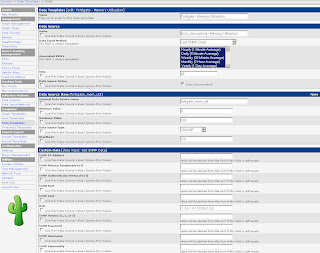
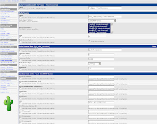
The Data Templates tell Cacti which values (OIDs) to monitor.
Next, go to Graph Templates in the Templates section. As before click Add in the top right corner and define the following two Graph Templates: Fortigate – System Resources and Fortigate – Total Sessions. The System Resources graph will monitor CPU and memory utilization in one combined graph.


Next create a Host Template as per the screenshot below.

Now you are ready to start monitoring firewalls. Under Management go to Devices and click Add. Define a new device. Sample values are in the screenshot.
 That’s it. Graphs will start to update after Cacti’s next polling cycle.
 That’s it. Graphs will start to update after Cacti’s next polling cycle.
Firewall Cleanup - Unused Policies
If you are running FortiOS 3.0 MR5 Patch 3 and later an easy way to see if your firewall policies are still being used is to modify the "Column Settings" under Firewall -> Policy. Select "Count" and click the right arrow to move it from "Available fields" to "Show these fields in this order".

Now your policies will show the "Count" column with indicates the number of times the policy has been invoked and the number of bytes transferred. Start your investigation with any rules that are "0/0" (i.e. not in active use) and continue by working on rules that have a low hit/byte count.

Subscribe to:
Comments (Atom)
